|
|||||||||||||||||||||||||||||||||||||||||||||||||||||||||||||||
Two steps furnace internal pressure control loops
LOOP
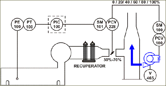
The furnace internal pressure control loop is shown schematically in the diagram above. The ideal pressure in a given furnace is a trade off solution in which the sum of hot gas losses and the cool air infiltration is minimized. The optimum pressure for most of the furnaces is about + 0,10 to 0,50 mm H2O measured at hearth level. This value must be determined through smoke testing in the furnace discharge door. The final value depends on the position of the probe or pressure tap. Gases formed by combustion are aspirated to the waste gas discharge flue and cross the tube banks of the recuperator pipe clusters A and B, where they give off part of their residual heat to the combustion air running inside the tubes. After the recuperator, they follow through the channel to the stack, where they are delivered to the atmosphere. This aspiration is obtained by the ejector installed on the bottom of the chimney, which, by injecting cool air from fan V-465, causes a suction inside the chimney. Internal pressure is controlled by control loop PIC-100 and displayed on the video monitor. The 4 to 20 mA signal from the transmitter is converted into a digital value in the electronic system A/D converter (Analog/Digital), ranging from 0 to 1000 bits.
The transmitter range is then:
As the furnace internal pressure increases, the routine in the electronic system, named here PIC-100, determines the error: error = furnace pressure - desired pressure and calculates the correction according to the parameters set in the associated PID routine. It is clear that the control action is direct, because, as the pressure increases, so does the output because the error is positive, opening the valve. The output increment (decrement) and positioning follow the same criteria described above, under Fuel-Air Ratio Control. The control output is directed to butterfly valve PCV-228 located between recuperator and the chimney. The variation is from 0 to 100 % valve aperture. When the output reaches the value of 70%, a one-step opening command is issued to radial valve PCV-100, located in the induced draft fan suction V-465, according to the relationship below. Similarly, when the output reaches the value of 30%, a one-step closing command is issued to valve PCV-100, located in the induced draft fan suction V-465, according to the relationship below:
This way, only when the butterfly in the smoke pipeline is out of its optimum linear range (between 30 and 70%), the radial valve in the induced draft fan suction will actuate. This one always operates in steps, that is, it guarantees the smoke aspiration (coarse tuning) and the butterfly guarantees the furnace internal pressure (fine tuning). In order to start the motor of fan V-465, it is necessary that radial valve PCV-100, in the fan suction, is closed. The position of this valve is displayed on the video monitor. The open valve alarm is activated by the supervisory module, and the valve position is informed by potentiometer ZE-100 of servomotor SM-100. |
|||||||||||||||||||||||||||||||||||||||||||||||||||||||||||||||
|


